

Last week was an interesting one. We have been playtesting the first instruments, and seeing what kinds of variations there are due to component tolerances. We have put together ten Soundplanes now, and this gives us the novel capability to look at the differences between them and work to reduce sources of noise. So we're taking some time this week for tuning the client software based on what we're learning, and finding the best carrier frequencies for all the instruments.
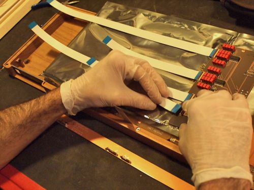
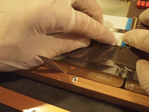
Attaching FFC (flat flexible cables) to the main board. All the red things are precision capacitors for the carrier circuits.
A closeup of the assembly showing sensor boards and the main board. At center is one of the aluminum thread inserts that hold the bottom of the instrument. The combination of CNC milling and metal thread inserts makes the Soundplane's slim yet rigid structure possible.
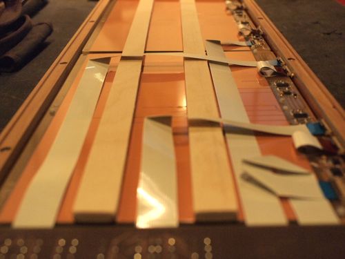
Looking down the instrument with the main board out of focus in front. The long rails are spacers that hold the sensors away from the aluminum back. Made on the thickness planer, they are 0.230" thick, give or take 0.005".
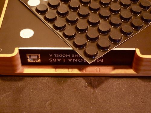
The last step before playtesting: attaching the LRFs (Little Rubber Feet). The feet fit into small depressions in the back so they won't go anywhere. I tried five different kinds of feet that claimed to be 1/2" in diameter. Only the 3M brand Bumpons ended up fitting accurately into the milled spaces. Yay 3M.